How to re-pin RC Car servo? If your servo plug doesn’t fit your receiver, or you picked up a servo from a different manufacturer, you may need to re-pin the connector. This sounds technical, but with a little patience, it’s something any RC hobbyist can do at home. This guide covers everything you need to know about the soldering required.
What Does “Re-Pinning” Mean?
Re-pinning means physically removing the tiny metal pin connectors from inside a servo plug and putting them back in a different order. Different RC brands use different pin arrangements, and if the pins don’t match your receiver, the servo won’t work (or worse, could get damaged).
The three pins in a servo connector are:
- Signal (white or yellow wire)
- Positive/Power (red wireusually +5V)
- Negative/Ground (black or brown wire)
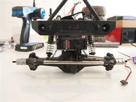
The order these pins sit in the connector changes between brands. Futaba, JR, Hitec, and others all have slightly different arrangements.
What You’ll Need
- A pin removal tool (a plastic spudger, a thin flathead screwdriver, or a store-bought servo connector tool works fine)
- Good lighting
- A magnifying glass (optional but helpful for beginners)
- Your servo and receiver manual (to confirm the correct pin order)
How to Re-pin Rc Car Servo?
Step 1: Identify the Pin Order You Need
Before you start, you need to know two things:
1. What order are the pins currently in?
2. What order do you need them in?
Look at your receiver’s servo port. Most receivers have a small label or diagram showing the pin arrangement (signal, positive, ground). If not, check the receiver manual or the manufacturer’s website.
Common arrangements:
- Futaba: Ground – Positive – Signal (brown, red, orange)
- JR/Spektrum: Signal – Positive – Ground (white, red, black)
- Hitec: Signal – Positive – Ground (yellow, red, black)
Step 2: Look at the Connector
Hold the servo connector with the locking tab facing up. You’ll see a small rectangular plastic housing with three holes, one for each pin. Each pin has a tiny metal tooth (a retaining tab) that locks it in place inside the housing.
Step 3: Release the Locking Tab on the Connector
Most servo connector housings have a small locking tab on the end. Gently press this tab down (or up, depending on the connector type) while pulling on the wire. This releases the whole connector from any clip it may be attached tobut it does NOT release the individual pins.
Step 4: Remove the First Pin
Insert your pin removal tool into the connector housing on the side of the pin you want to remove. You’re looking for the tiny metal retaining tab inside the channelyour tool needs to press this tab flat so the pin can slide out.
- Gently push the tool in (don’t force it)
- Feel for the slight give as the retaining tab releases
- Pull the wire from the back at the same timethe pin should slide out cleanly
Do this for each pin, one at a time. Keep track of which wire was in which position.
Step 5: Re-Insert the Pins in the New Order
Now insert each pin into the correct hole in the housing in the new order. Push firmly until you feel (and sometimes hear) a small clickthat’s the retaining tab snapping back into place.
Pull lightly on each wire to make sure the pin is locked. If it slides out easily, it didn’t click in properlytry again.
Step 6: Test Before You Drive
Before putting everything back together, connect the servo to the receiver and power up the system. Move the steering wheel (or throttle) to make sure the servo responds correctly and moves in the right direction. If it moves the wrong way, you may need to reverse it in your transmitter or check the signal wire placement.
Common Re-Pinning Mistakes
Mistake 1: Forcing the toolIf you push too hard, you can damage the retaining tab or the housing. Use gentle pressure.
Mistake 2: Not confirming the correct pin order firstAlways double-check before you start. Getting it wrong can mean the servo gets power on the signal wire, which can fry it.
Mistake 3: The pin doesn’t clickIf the pin slides back out when you tug it, it isn’t seated properly. Remove and reinsert with more pressure.
Mistake 4: Mixing up the wiresLabel your wires with a small piece of tape before you remove them, especially if you’re moving all three at once.
When Should You Re-Pin Instead of Buy a New Plug?
Re-pinning is the right move when:
- You have a quality servo that works perfectly but has the wrong plug
- You want to avoid cutting and soldering wires
- You only need to change the pin order, not the whole connector type
If the connector body itself is damaged, cracked, or broken, it’s easier to replace the whole connector with a new one.
Final Thoughts
Re-pinning a servo connector is a quick skill that every RC hobbyist should know. It takes about ten minutes once you’ve done it a couple of times, and it saves you from buying a new servo or butchering wires with a soldering iron. Go slowly, confirm your pin order first, and don’t rush the clickthat little snap is your confirmation that the pin is seated properly.
Frequently Asked Questions (FAQ)
Do I need to solder anything to re-pin a servo?
No. Re-pinning only involves moving the metal pins inside the plastic housing. No soldering is needed.
What tool do I use to push the pins out?
A dedicated servo connector pin removal tool is ideal, but a thin flathead screwdriver, a sewing pin, or a mechanical pencil lead (without the pencil) also work in a pinch.
What if I push a pin in too far and it goes through the other side?
It happens. Use a pair of fine-tipped tweezers to retrieve the pin, check it’s not bent, and try again.
Can re-pinning damage my servo?
Only if you put the pins in the wrong order and power it incorrectly. Always verify the pin order before powering up.
Is the pin order the same for all servos?
No. Different brands have different orders. Always check both your servo and receiver’s specifications.
What’s the easiest way to remember pin order?
A simple rule: Ground is almost always on the outside edge of the plug (the side away from the locking tab). Signal is on the other edge. Positive (red) is in the middle.
Can I use electrical tape instead of re-pinning?
Not really. Electrical tape can keep a connector plugged in but won’t fix a wrong pin arrangement.